
An ESP32 board has around 38 pins, but not all of them behave the same way. Some are used by the internal flash memory, some decide how the chip boots and some can only read signals. As a result, if you pick the wrong one, your project may refuse to boot or the upload may fail for no obvious reason.
This guide explains which ESP32 pins are safe to use on the popular ESP32 WROOM-32 development boards, which ones need care and which ones to avoid completely. So, keep it open next to your breadboard.
Quick Answer: ESP32 Pins Safe to Use
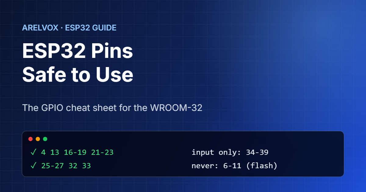
If you only want the short version, these GPIOs work as normal inputs and outputs on an ESP32 WROOM-32 board, without surprises at boot:
- GPIO 4, 13, 16, 17, 18, 19, 21, 22, 23, 25, 26, 27, 32 and 33
In total, that gives you 14 reliable pins, which is enough for most projects. Pins 14 and 15 also work. However, they briefly output a signal at boot, so they are not ideal for relays. The sections below explain the rest.
🛒 What you need
As an Amazon Associate, Arelvox earns from qualifying purchases. This does not change the price you pay.
Pins You Should Never Use
GPIO 6 to 11 are connected to the SPI flash chip that stores your program. If you use them, the ESP32 crashes or will not boot. In fact, many boards do not even break them out, and that is a good thing.
Similarly, GPIO 1 and 3 are not ESP32 pins safe to use in normal projects. They are TX and RX of the main serial port, which is used for uploading code and for the serial monitor. You can use them in an emergency, but you lose your logs and may break uploads, so avoid them.
Strapping Pins: Are These ESP32 Pins Safe to Use?
When the ESP32 starts, it reads a few pins to decide how to boot. These are called strapping pins, and anything you connect to them must not pull them the wrong way at power-up:
- GPIO 0: must be high to run your program. Pulling it low enters download mode, which is exactly what the BOOT button does.
- GPIO 2: must be low or floating for uploads. On many boards it drives the onboard LED.
- GPIO 5: controls a boot timing setting. It is usually fine as an output.
- GPIO 12: sets the flash voltage. If something pulls it high at boot, the ESP32 may not start. Avoid it unless you know what you are doing.
- GPIO 15: controls boot messages. It is fine for most uses.
As a result, buttons and sensors that pull a pin high or low are better connected to one of the safe pins above.
Input-Only Pins: GPIO 34 to 39
GPIO 34, 35, 36 (often labeled VP) and 39 (VN) are ESP32 pins safe to use only as inputs. In other words, they cannot drive an LED or a relay, and they have no internal pull-up or pull-down resistors, so a button needs an external resistor. On the other hand, they are excellent analog inputs, which makes them perfect for reading sensors or a battery voltage through a voltage divider.
Analog Pins and the Wi-Fi Catch
Which ESP32 pins are safe to use for analog readings? The ESP32 has two analog-to-digital converters. ADC1 uses GPIO 32 to 39. ADC2 uses GPIO 0, 2, 4, 12 to 15 and 25 to 27. Here is the catch: ADC2 does not work while Wi-Fi is on, because the radio uses it. Since most ESP32 projects use Wi-Fi, you should therefore use ADC1 pins (32 to 39) for analog readings.
Also remember that the ESP32 pins work at 3.3 V. For the full electrical details, check the official ESP32 datasheet from Espressif. Never connect a 5 V signal directly, because it can damage the chip. Use a level shifter or a voltage divider instead.
Default Pins for I2C, SPI and UART
Thanks to its pin matrix, the ESP32 can move most functions to almost any pin, but these defaults are what libraries and ESPHome expect, so using them saves time:
- I2C: SDA = GPIO 21, SCL = GPIO 22
- SPI (VSPI): MOSI = 23, MISO = 19, SCK = 18, CS = 5
- UART2: RX = GPIO 16, TX = GPIO 17
- PWM: any output-capable pin
For example, our washing machine alert connects an MPU6050 to GPIO 21 and 22, and our mmWave presence sensor uses GPIO 16 and 17 for the radar. In both cases, we picked ESP32 pins that are safe to use and match the defaults.
How Much Current Can ESP32 Pins Safely Supply?
In general, each ESP32 GPIO can supply roughly 20 mA safely, and the chip as a whole has a limit too. That is enough for an LED with a resistor, but not for motors, relays without a driver board or LED strips. To pick the right LED resistor for a 3.3 V pin, use our LED resistor calculator.
FAQ: ESP32 Pins
Which ESP32 pins are safe to use?
On an ESP32 WROOM-32 board, GPIO 4, 13, 16 to 19, 21 to 23, 25 to 27, 32 and 33 work as normal inputs and outputs without boot problems.
Why does my ESP32 not boot when something is connected?
You are probably using a strapping pin such as GPIO 0, 2 or 12, and your circuit pulls it the wrong way at power-up. Move the connection to a safe pin.
Can I use GPIO 34 as an output?
No. GPIO 34 to 39 are input-only and have no internal pull-up or pull-down resistors.
Why does analogRead not work with Wi-Fi on?
ADC2 pins cannot be used while Wi-Fi is active. Use ADC1 pins, which are GPIO 32 to 39.
Are ESP32 pins 5V tolerant?
No. ESP32 GPIOs work at 3.3 V. Use a level shifter or a voltage divider for 5 V signals.
2 thoughts on “ESP32 Pinout Guide: Which GPIO Pins Are Safe to Use?”